A while back, my TV wouldn’t turn on, so I had a repair technician replace the motherboard. I kept the old one.
With some free time on my hands these past few days, I took a closer look at it and noticed that the screw holes used to secure both this TV motherboard and a PC motherboard are copper-free (when I tested them with a multimeter, there was no electrical continuity between the inner walls of the screw holes and the motherboard’s ground (GND)).

This can lead hardware engineers to mistakenly believe that “motherboard screw holes are not grounded.”
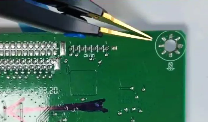
After all, most motherboard screw holes are grounded, and they typically contain copper, as shown in the image below.
It’s quite strange to suddenly see copper around the outer edge of a mounting hole but none inside it!

To fully understand why this is the case, we need to analyze the true reasons behind the design of copper-free screw holes on motherboards from the perspectives of PCB design, manufacturing processes, electromagnetic compatibility (EMC), and structural reliability.
Common misconceptions and clarifications are provided at the end of this article.
Clarification of a Key Concept: Electrical Grounding of Screw Holes
First, it is important to establish a fundamental fact: the design objective of screw holes on TV and PC motherboards is to provide an electrical connection to the motherboard’s signal ground (GND), not to isolate it.

The “signal ground” (GND) on the motherboard serves as the reference point for all voltages in the system.
The “chassis ground,” on the other hand, refers to the metal chassis itself.
The motherboard connects its GND network to the chassis via screws and copper pillars, which are ultimately connected to the earth through the power cord, forming a complete grounding system.
Why do the Inner Walls of Screw Holes “Appear to be Ungrounded”?
As mentioned above, using a multimeter to measure the inner walls of the holes reveals no continuity with the motherboard’s GND—this is the most common source of misunderstanding.
The reason lies in PCB manufacturing considerations, not electrical design intent.
1. Determined by Manufacturing Process: Use of Non-Plated Through Holes (NPTH)
The vast majority of consumer-grade motherboards use non-plated through holes (NPTH) for screw holes:
Process: After drilling, the hole walls are not electroplated with copper; therefore, the hole walls themselves are made of insulating base material (such as FR-4 fiberglass).
Core Purpose: To prevent solder from flowing along the hole walls during wave soldering, which could block the screw holes.
Electrical Connection Method: Although the hole walls lack copper, the annular pads surrounding the hole openings directly connect to the motherboard’s inner or outer layer ground (GND) network, as indicated by the arrows below.
When a metal screw passes through and tightens the through-hole pad, the solder on the pad tightly contacts the screw head and the copper pillar, forming a reliable electrical connection.
Therefore, the electrical path is: motherboard GND → through-hole pad → screw → copper pillar → chassis, rather than through the wall of the hole.
2. Special Treatment for Plated Through Holes (PTH)
A small number of high-end or server motherboards use plated through holes (PTH) to enhance mechanical strength.
In this case, copper coats the hole walls and makes solder climb up the walls during wave soldering.
However, manufacturers use physical methods such as peelable blue adhesive to seal the hole openings during soldering and prevent solder from blocking the screw holes.
Why is Multi-Point Grounding Necessary?
All screw holes on the motherboard connect to GND, and the metal chassis short-circuits them, forming a typical multi-point grounding system.
In digital circuit design, this is an advantage rather than a flaw—it serves as a necessary requirement for electrical performance, as explained below.
1. Reduce ground impedance

In high-frequency digital circuits, ground lines exhibit inductive characteristics.
Multi-point grounding can significantly reduce the equivalent inductance between the ground plane and the chassis;
Connecting multiple points in parallel significantly reduces the total inductance L, thereby lowering the high-frequency impedance, which benefits signal integrity and electromagnetic compatibility.
2. Creating a Complete Shielded Enclosure
A metal chassis acts as a Faraday cage and requires a low-impedance connection to the motherboard’s GND for effective shielding.
Multi-point grounding maintains a uniform potential across all parts of the chassis and the motherboard’s GND, prevents external interference from creating a potential difference between the chassis and the motherboard, and enables the chassis to efficiently dissipate internal high-frequency noise.

3. Analysis of Ground Loop Issues
The statement “Multi-point grounding can create ground loops that introduce interference” raises a common theoretical concern, but PC systems require analysis in the context of practical applications.
Power cords primarily introduce power-frequency interference (50/60 Hz); the power supply’s Y-capacitor and grounding design address this interference, and the number of screw holes has little influence on it.
High-frequency interference: The potential difference between the chassis and the motherboard GND is extremely small (due to the extremely low impedance of multiple connections), making it difficult to form an effective loop antenna.
Practical verification: Retaining only a single-point ground makes the chassis a floating conductor and increases its susceptibility to external noise coupling.
The motherboard GND connects to the chassis via multiple parallel paths (a tree-like multi-point grounding structure), with the chassis acting as a low-impedance busbar that ultimately connects to earth ground.
Five Key Engineering Considerations for Screw Hole Design
1. Manufacturing Reliability (Preventing Hole Blockage)
Issue: During wave soldering, solder tends to flow along the walls of PTH holes, causing them to become blocked.
Solution: Use an NPTH design, where the hole walls are free of copper, preventing solder from adhering.
Result: Ensures assembly yield and prevents installation failures caused by blocked holes.
2. Mechanical Strength and Impact Resistance
Design Details: Place multiple small vias (via stitching) or cutouts around the pad at the hole opening.
Purpose:
Connect the copper foil layers to enhance the pad’s peel resistance
Distribute mechanical stress during screw tightening
Reduce the risk of material fatigue under thermal cycling

3. Electrical Safety and Isolation Protection
Risk Scenario: Screws or copper pillars shift slightly due to vibration, coming into contact with traces or copper foil around the hole openings.
Preventive Measures:
Prohibit the routing of non-GND traces within a certain radius of screw holes (maintain a clear zone).
Apply solder mask to enhance insulation.
NPTH design fundamentally prevents accidental short circuits between the hole walls and internal layers.
A few years ago, I heard that on PC motherboards, the outer ring of screw holes had suffered damage to the solder mask and short circuits due to screw tightening, resulting in abnormal startup.
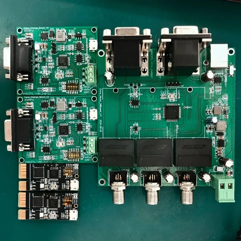
TV motherboards integrate power, signal, and display drivers into a single board.
On these boards, “hot ground” holes serve only mechanical fastening and provide no electrical connection.
The matrix holes on the right handle high current and dissipate heat.

4. Electrostatic Discharge (ESD) Protection
Discharge Path: Static electricity flows from the chassis → screw → via pad → motherboard GND → ESD protection device → chip
Design Considerations: Ensure the path has low impedance and is short in length to prevent static electricity from traversing sensitive areas
Advantages of NPTH: Insulated via walls prevent static electricity from coupling directly to signal lines in intermediate layers along the via walls.
5. Thermal Management Support
Screw holes and surrounding copper foil can assist in heat dissipation by conducting heat from the motherboard to the chassis.
Multiple contact points create multiple heat conduction paths, reducing temperatures at local hotspots.
Another useful tip allows identification of refurbished or brand-new motherboards by examining the solder on the screw holes.
On a brand-new motherboard, the solder around the screw holes is full and smooth, with no signs of screw heads.
Comparison of Common Design Styles
A screw hole on a PCB is a packaged pad. In design software, three methods actually configure this pad; the table below outlines their differences and uses.
| Type | Hole Wall | Electrical Connection | Advantages | Application Scenarios |
|---|---|---|---|---|
| NPTH | No Copper | Conducted through solder pad contact | Low cost, prevents solder wicking, simple process | Most consumer-grade motherboards |
| PTH + Return Pad | Copper Plated | Hole wall conducts to designated layers | High mechanical strength, reliable grounding | Servers, industrial control motherboards |
| Thermal Relief Pad | Copper Plated | Solder pad connected through thermal relief spokes | Easy soldering, controllable heat dissipation | High-current grounding points |
Common Misconceptions and Clarifications
Misconception 1: Only one screw hole on the motherboard actually connects to ground!
Fact: On the vast majority of motherboards, pads at the hole openings connect all screw holes to GND.
This is a full-hole grounding design. Multi-point grounding is a standard practice in digital circuits.
Misconception 2: Screw holes do not isolate signal ground from chassis ground!
Fact: On the contrary, the purpose of screw holes is precisely to connect signal ground to chassis ground.
The absence of copper in the holes is due to manufacturing processes and does not indicate an intent for electrical isolation.
Specific environments requiring isolation need an insulating spacer under the screw.
Misconception 3: An RC network (1MΩ + 10nF) is standard for motherboard screw holes!
Fact: Audio equipment and precision instruments commonly use this single-point isolation design to isolate digital ground from shielding ground.
PC motherboards typically use a direct, low-impedance connection, as the power supply internally connects GND to PE.
Summary
The design of screw holes on PC motherboards is the result of multiple factors, including electrical performance, manufacturing processes, mechanical reliability, and safety standards:
Electrical objectives: Connect the motherboard’s GND to the chassis via multiple low-impedance paths to form a complete shielding and reference plane.
Manufacturing implementation: Use the NPTH process to prevent hole blockage and establish electrical connections via pads at the hole openings.
Safety protection: Techniques such as clearance zones, solder mask, and reverse pads prevent accidental short circuits.
EMC Considerations: Multi-point grounding reduces high-frequency impedance and enhances the system’s immunity to interference.
Understanding the design principles behind screw holes not only dispels the misconception of “no grounding” but also provides a deeper grasp of the overall logic of grounding and shielding in PC hardware systems.
For hardware designers, this serves as a classic case study in EMC design;
For repair technicians and DIY enthusiasts, it forms the foundation for correctly diagnosing grounding-related faults.