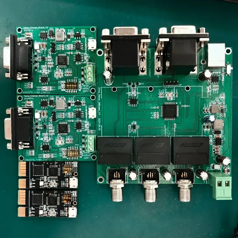
Inside 5G base stations, millimeter-wave radar systems, and satellite communication equipment, high-frequency signals travel at a rate of billions of times per second.
In this invisible electromagnetic battle, PCBs are no longer merely “carriers of circuit connections,” but rather the foundation of the entire system’s performance and the first line of defense for signal integrity.
Standard FR-4 laminates are still adequate for frequencies below 1 GHz, but once frequencies rise to 5G, millimeter-wave, or even higher bands, their dielectric constant begins to fluctuate significantly, the loss factor increases sharply, and signal attenuation and timing jitter follow.
A microstrip line originally designed for 50Ω impedance may deviate from the design value if the board’s dielectric constant is unstable, leading to reflections and standing waves that instantly compromise the entire link.
The difference between high-frequency PCBs and standard PCBs goes far beyond simply being “a little more expensive.”
Below, we break down the fundamental differences between the two from four dimensions: materials, design, manufacturing, and testing.
Differences in Materials
Dielectric constant and loss factor: the two numbers that determine the “life or death” of a signal.
The most fundamental difference between high-frequency PCBs and standard PCBs lies in the base material.
Standard FR-4 boards use epoxy-impregnated glass fiber cloth as their base material, which has a relatively high dielectric constant (typically ranging from 4.2 to 4.8) and significant dielectric loss.
When signal frequencies exceed 1 GHz, dielectric loss increases significantly, and the dielectric constant fluctuates markedly with frequency, making impedance control extremely difficult.
In contrast, high-frequency boards utilize specialized resin systems (such as polytetrafluoroethylene, hydrocarbons, and ceramic fillers), which offer a more stable dielectric constant and a lower loss tangent.
They maintain consistent electrical parameters across a wide frequency band, fundamentally ensuring the transmission quality of high-speed signals.
Lieban has established a comprehensive supply system in the high-frequency laminate sector, covering mainstream high-frequency substrates such as the Rogers series (RO3000, RO4000, etc.), the Taiyao series, and the Isola series, while also supporting customization and hybrid lamination of halogen-free high-frequency materials.
For standard FR-4, Lieban selects Grade A laminates from leading brands such as Kingboard and Shengyi, all of which meet the 94V0 flame retardancy rating—the highest internationally recognized standard for flame retardancy.
This comprehensive material system enables Lieban to flexibly address the diverse substrate requirements of various applications, including automotive radar, 5G communications, and industrial control.
For projects requiring a balance between performance and cost, Hunter Board can also, based on customer needs, use high-frequency materials locally in critical signal areas while retaining FR-4 in other areas.
Through a precise lamination process, this heterogeneous lamination is achieved, optimizing overall costs while meeting signal integrity requirements.
Difference in Design: Impedance Control—From “Roughly Correct” to “Must Be Precise”
Impedance control for standard PCBs is relatively lenient;
A tolerance of ±10% is acceptable in many consumer electronics applications.
However, high-frequency circuits are extremely sensitive to impedance mismatches—even a 10% deviation can cause signal distortion, directly affecting communication quality.
The design of high-frequency PCBs must narrow impedance tolerances while strictly controlling the coordinated consistency of multiple parameters, including trace width, trace spacing, copper thickness, dielectric thickness, and dielectric constant.
Lieban’s capabilities in impedance control cover the entire process:
Theoretical Simulation
Based on the customer’s stack-up structure and material properties, the engineering team uses specialized software to perform impedance matching calculations and determine the optimal trace width and dielectric thickness.
Manufacturing Precision
We employ Laser Direct Imaging (LDI) technology, combined with etching compensation algorithms, to achieve high-precision pattern transfer.
Outer-layer trace widths and spacing can reach 2 mil/2 mil with 1/3 oz copper thickness and 2.5 mil/2.5 mil with 1 oz copper thickness;
These limits can be further reduced upon review. Inner layers also support fine traces of 2 mil/2 mil.
Tolerance Control
Impedance tolerance is typically controlled within **±10%**, meeting the requirements of the vast majority of high-frequency applications.
All impedance test strips are manufactured using the same coaxial materials, lamination, and etching processes as the mass-produced boards, rather than being produced as separate “sample strips,” ensuring that test results accurately reflect the actual performance of the product.
Process Monitoring
Professional impedance testers are used for initial inspection, in-process inspection, and final inspection during production to generate impedance test reports.
The test range covers 10–150 Ω for single-ended lines and 20–200 Ω for differential lines, with a measurement accuracy of **±1%** and a minimum resolution of 0.01 Ω.
Difference in Manufacturing: Conventional Processes Cannot Produce High-Frequency Boards
The manufacturing process for standard PCBs is relatively mature and offers high tolerance, but the processing of high-frequency boards imposes entirely different requirements on equipment and processes.
Drilling Process
High-frequency materials (especially PTFE-based materials) are extremely prone to “drilling debris” during the drilling process, and the roughness of the hole walls significantly affects transmission loss in high-frequency signals.
Lieban is equipped with CNC drilling machines from brands such as Dongtai and Han’s Laser, featuring a positioning accuracy of ±0.05 mm and an autonomous drilling accuracy of ±0.018 mm.
The minimum mechanical drill hole diameter is Φ0.15 mm, while the minimum HDI laser blind via diameter is Φ0.075 mm. PTH hole diameter tolerances are controlled within ±0.075 mm (±0.05 mm upon request), while NPTH hole diameter tolerances are ±0.05 mm, ensuring via quality meets high-frequency requirements.
Pattern Transfer
Traditional film exposure processes can no longer meet the precision requirements of high-frequency boards due to film expansion and contraction issues.
Lieban uses a laser LDI (Laser Direct Imaging) exposure system, with a line width resolution of up to 40 μm (1.6 mil) and an alignment accuracy deviation of ±10 μm, completely eliminating persistent problems associated with traditional processes such as short circuits, pattern expansion and contraction, and poor exposure.
The solder mask process also utilizes a laser LDI exposure system to ensure precise alignment between the solder mask and the circuit layer.
Standard solder mask offset tolerance is ±3 mil, with a customizable tolerance of ±2 mil.
Electroplating
The uniformity of via copper plating on high-frequency boards directly affects signal integrity.
Lieban uses fully automated vertical copper plating and electroplating lines from Taiwan’s Jingming, achieving copper plating uniformity of ≥97%, deep-hole plating capability of ≥90%, and a board thickness-to-via aspect ratio of up to 13:1.
The plating process uses microcrystalline phosphor bronze balls, which differ from the recycled copper scraps or copper blocks used in traditional factories;
The resulting copper plating offers superior density, ductility, and control of organic impurities.
The default via copper thickness is 18 μm (IPC Class 2 standard), with customizable options including 20 μm, 25 μm, 30 μm, 35 μm, and other grades to meet various reliability requirements.
Etching
Line width precision in high-frequency boards is a prerequisite for impedance control.
Lieban is equipped with a DES ultra-thick copper vacuum precision etching line, which employs a spray-type + vacuum etching process.
This effectively prevents the “beach effect” during chemical reactions, ensures the quality of thick copper traces, eliminates burrs and jagged edges, and prevents abnormalities in line width and spacing, as well as impedance issues and signal interference.
Lamination
The interlayer alignment accuracy of high-frequency mixed-pressure boards directly affects signal transmission quality.
Hunter Board has established a dedicated process parameter library for high-frequency materials, with precise process windows covering everything from drilling speed and feed rate to resin removal methods.
The interlayer alignment accuracy of multilayer boards can be controlled within ±3 mil, ensuring minimal loss during high-frequency signal transitions between layers.
Difference in Inspection: Standard Testing Fails to Detect High-Frequency Defects
Standard PCB inspection primarily relies on continuity testing, which simply determines whether the circuits are connected.
However, quality issues in high-frequency boards are often hidden in subtle details—such as thin copper in vias, localized circuit defects, and impedance drift—and these “near-open” issues cannot be detected by conventional two-wire testing.
AOI Inspection
Lieban is equipped with an in-line AOI (Automated Optical Inspection) system, offering a maximum detection resolution of 50 μm.
It is suitable for inspecting high-density, high-layer-count, and high-impedance products with trace widths as fine as 2 mils.
Additionally, the facility is equipped with an X-ray inspection system, which provides radiographic imaging to examine the inner layers, lamination, and drill hole alignment of high-layer-count boards, eliminating blind spots where inner-layer quality cannot be effectively monitored after lamination.
Four-Wire Low-Resistance Testing
This represents a significant upgrade that sets Hunter Board apart from industry standards.
Conventional two-wire flying probe testing achieves accuracy only at the Ω level, leaving detection blind spots for minute defects such as high resistance, foreign objects in via copper, and “near-open” circuits.
Lieban has upgraded its testing capabilities to four-wire low-resistance flying probe testing, achieving accuracy ranging from 0.1 μΩ to 0.1 mΩ.
By utilizing independent voltage circuits to eliminate contact resistance interference, this method excels at detecting high-resistance anomalies in “near-open” circuits and fluctuations in via copper resistance.
For high-reliability products such as automotive electronics and medical devices, four-wire low-resistance testing has become a critical means of ensuring quality.
Reliability Verification
Every batch of products undergoes solderability testing (wetting area greater than 95%, with plated through-holes fully wetted) and thermal shock reliability testing (288°C ± 5°C × 10 seconds × 3 times) to ensure the products can withstand the thermal stress of subsequent assembly and long-term service.
Differences in Applications: In Which Scenarios Are High-Frequency PCBs Essential?
Standard PCBs are suitable for consumer electronics, home appliances, low-frequency control circuits, and similar applications.
High-frequency PCBs, on the other hand, are used in fields that demand extremely high signal integrity:
Automotive Electronics
77 GHz millimeter-wave radar and ADAS (Advanced Driver Assistance Systems) require low-loss materials such as the Rogers RO3000 series.
5G Communications
Base station RF modules and antenna arrays operate in frequency bands such as 3.5 GHz, 26 GHz, and 28 GHz, and have stringent requirements for impedance consistency and insertion loss.
Industrial Control and Energy Storage
High-frequency switching power supplies, precision measurement equipment, and high-voltage isolation testing require stable dielectric properties and dielectric strength.
Embodied Robotics
High-precision sensor signal processing and real-time control buses require signal latency and jitter to be controlled at the nanosecond level.
Lieban has obtained ISO 9001 and IATF 16949 quality management system certifications, as well as product certifications such as RoHS, REACH, and UL.
The company operates two self-owned production bases in Zhuhai with a total floor area exceeding 25,000 square meters.
Equipped with over 520 units of advanced manufacturing equipment, these facilities have an annual combined production capacity of 800,000 square meters and are capable of full-chain delivery—from prototypes and small-to-medium batches to mass production.
From Materials to Delivery: The Secret to High-Frequency PCB Quality
The differences between high-frequency PCBs and standard PCBs are evident at every stage, from material selection to final delivery.
The dielectric constant and loss factor of standard FR-4 become unstable at high frequencies, whereas high-frequency PCB materials achieve consistency in electrical parameters across a wide frequency band through the use of specialized resin systems.
While an impedance tolerance of ±10% is acceptable for standard PCBs, high-frequency boards require even finer trace width control and stricter lamination processes within the same tolerance range to ensure that actual values do not deviate.
Standard testing can determine continuity, but high-frequency testing must be capable of detecting impedance anomalies at the micro-ohm level.
Liebang’s experience in the high-frequency PCB sector demonstrates that the competitiveness of high-frequency boards is fundamentally a reflection of comprehensive capabilities in materials science, precision manufacturing, and standardized testing.
From the comprehensive supply of high-frequency laminates—such as Rogers, Taiyao, and Isola—to the full chain of precision processes including LDI (Laser Direct Imaging), vacuum etching, and four-wire low-resistance testing, all the way to IATF 16949 automotive-grade quality system certification—every step points toward the same goal: ensuring that the impedance, loss, and delay of every transmission path are precisely controllable when signal frequencies exceed the GHz range.
The answer lies in the selection of materials, in the precision of the equipment, in the control of every production step, and even more so in the rigorous series of tests conducted before the products leave the factory.