Optical modules are critical products in the field of optical communications and are widely used in high-performance data centers, communication networks, large-scale computing, and cloud computing.
Optical module printed circuit board (PCB) products with transmission rates of up to 400 Gbit/s (400G) offer advantages such as high transmission speeds, long transmission distances, high integration, compact size, and low power consumption.
They not only meet the requirements of cloud computing and big data development—including high bandwidth, low latency, and high reliability—but are also suitable for long-distance transmission, high-speed transmission.
Currently, the market demand for 400G optical modules continues to grow, but the actual manufacturing complexity of such products is increasing, posing significant challenges for design and production.
To address this, this study develops a new type of 400G optical module PCB product, focusing on resolving technical issues such as the fabrication of second-order high-density interconnect (HDI) products, control of the top width of bonded striplines, and impedance control.
This provides fabrication experience for such production boards and better serves the optical communications industry.
Design Considerations for 400G Optical Module PCBs
Basic Structure
(1) 10-layer Class II HDI board, finished board thickness 1.0 mm, surface finish: electroless nickel/electroless palladium/immersion gold (ENEPIG).
(2) Minimum line width is 0.09 mm, minimum spacing is 0.10 mm, and signal lines have impedance requirements.
(3) Through-holes include through-holes, buried vias, and blind vias.
The 0.15 mm/0.20 mm through-holes are processed using a split-hole method, following a laser-drilled blind via + buried via + laser-drilled blind via structure.
The laser-drilled blind via diameter is designed to be 0.1 mm, and the buried via diameter is machined to 0.15 mm.
Performance Characteristics
(1) High-speed signal impedance-controlled traces are routed on the top layer, bottom layer, L3 layer, and L8 layer, with all impedance values maintained within ±10%. For example:
① Top layer: two types of differential pair transmission lines with trace widths/spacing of 0.098/0.101 mm and 0.122/0.173 mm, both with impedance controlled at 100 Ω ±10%;
② L3 and L8 layers: 0.093/0.202 mm, with impedance controlled at 100 Ω ±10%;
③ Bottom layer: differential pair transmission lines with a line width/spacing of 0.122/0.173 mm, with impedance controlled at 100 Ω ±10%.
(2) The line width at the top must be controlled in the areas marked on the drawings: in the blue areas, the copper surface flatness must not exceed 10 μm;
In the red areas, the bonding pads must meet a minimum width of 100 μm, and the copper surface dimensions on the etched bonding pads must not be less than 80 μm.
Manufacturing Challenges
(1) The outer layers of this 10-layer, second-order HDI board feature a resin-filled via with electroplated caps (POFV) design.
Buried vias and HDI stacked vias are used to replace resin-filled vias in order to optimize the stackup design.
(2) This product has design specifications requiring a characteristic impedance and a minimum bond pad wire width of ≥80 μm; specific manufacturing processes must be planned accordingly.
(3) The finished product’s positioning marks must be perfect circles with no irregular defects.
The board’s structural features include second-order HDI blind vias, characteristic impedance, and hot-swap capabilities.
It is a PCB product for 400G optical modules, comprising three major functional zones: the plug-in connection area, the data rate feature area, and the component mounting area.
Preliminary Planning and Design
Layer Stack Design
The original 10-layer Class II HDI board used the “plating over filled via” (POFV) process for its outer layers.
To optimize the production process and reduce costs, the layer stack was redesigned to use buried vias combined with HDI stacked vias to replace the resin-filled vias.
According to the optimized stackup scheme, the L4–L5 and L6–L7 inner core boards are manufactured first, followed by lamination to form layers L3–L8.
Finally, layers L2–L9 and L1–L10 are produced through lamination and laser drilling (see Figure 1).

Hole Diameter Design
To address the issue of diameter variations in laser drilling within the same layer, the 0.15/0.20 mm through-holes were broken down into a structure consisting of a laser-drilled blind hole + buried via + laser-drilled blind hole for processing.
The laser aperture range of the drilling equipment used is 0.0750–0.1500 mm, and since the original design already included a large number of 0.1143 mm holes, the laser blind holes in each layer were processed with a diameter of 0.1000 mm, while the buried holes in layers L3–L8 were processed with a diameter of 0.15 mm. The changes in hole diameters are shown in Table 1.
| Drill Layer | Original Hole Diameter (mm) | Original Hole Count | Type | Optimized Drill Layer | Optimized Hole Diameter (mm) | Optimized Hole Count | Type |
|---|---|---|---|---|---|---|---|
| L1-L2 | 0.1143 | 882 | HDI Blind Via | L1-L2 | 0.100 | 1,676 | HDI Blind Via |
| L1-L2 | 0.1524 | 24 | HDI Blind Via | L1-L2 | 3.048 | 6 | NPTH |
| L1-L2 | 0.2032 | 794 | Through Hole | — | — | — | — |
| L1-L2 | 0.4064 | 144 | Mounting Hole | — | — | — | — |
| L1-L2 | 3.0480 | 6 | Non-Plated Through Hole (NPTH) | — | — | — | — |
| L2-L3 | 0.1143 | 1,033 | HDI Blind Via | L2-L3 | 0.100 | 1,827 | HDI Blind Via |
| L3-L8 | 0.1524 | 604 | Mechanical Buried Via | L3-L8 | 0.150 | 1,398 | Mechanical Buried Via |
| L8-L9 | 0.1016 | 8 | HDI Blind Via | L8-L9 | 0.100 | 1,909 | HDI Blind Via |
| L8-L9 | 0.1143 | 1,107 | HDI Blind Via | — | — | — | — |
| L9-L10 | 0.1016 | 8 | HDI Blind Via | L9-L10 | 0.100 | 1,770 | HDI Blind Via |
| L9-L10 | 0.1143 | 968 | HDI Blind Via | — | — | — | — |
Table 1. Hole Size Design
Impedance Simulation
To meet the differential line impedance requirements, the Polar Si9000PCB software was used to simulate the theoretical impedance values.
The top-layer impedance lines were calculated using the windowed model.
The copper thickness for L1 and L10 layers were calculated using a copper thickness of 25 μm, L2 and L9 layers using 30 μm, and L3 and L8 layers using 28 μm;
In the impedance calculations for layers L3, L8/L1, and L10, the upper layer trace width = lower layer trace width − 0.015 mm.
The final simulation results all meet the differential line impedance requirements.
Layer L1, trace width/ spacing of 0.122/0.173 mm, with an impedance requirement of 100 Ω ± 10%; the results are shown in Figure 2.
L1 layer, trace width/spacing of 0.098/0.101 mm, with an impedance requirement of 100 Ω ± 10%; the results are shown in Figure 3.


Layer L3, trace width/spacing of 0.093/0.202 mm, impedance requirement of 100 Ω ± 10%; the results are shown in Figure 4.
Impedance simulation:Layer L8, trace width/spacing of 0.09/0.20 mm, impedance requirement of 100 Ω ± 10%; the results are shown in Figure 5.
Layer L10, trace width/spacing of 0.122/0.173 mm, impedance requirement of 100 Ω ± 10%; the results are shown in Figure 6.


Process Flow Design
First, prepare the patterns for the inner core layers (Layers L4–L5 and L6–L7); then laminate the inner core layers to form layers L3–L8;
Further use the HDI lamination method to produce layers L2–L9; finally, laminate to produce layers L1–L10.
Key Process Design
Based on the characteristics of the 400G optical module PCB product, the key process design is shown in Table 2.
| No. | Process | Control Item | Control Requirement | Control Method | Actual Production Result |
|---|---|---|---|---|---|
| 1 | Inner Layer Imaging | Alignment exposure; acidic etching | Inner-layer circuit line width control: (0.07 ± 0.01) mm | Use Orbotech equipment for inner-layer pattern exposure and acidic etching; verify the first article before production. | Line width: 0.08 mm |
| 2 | Desmearing | Copper thickness uniformity; desmear amount | Surface copper thickness control: (17 ± 3) μm | Measure the copper foil at nine points on each panel to ensure the copper thickness remains within the specified range. | Maximum: 19.84 μm;Minimum: 15.92 μm;Average: 17.50 μm |
| 3 | Resin Plugging | Plug-hole recess | Plug-hole recess ≤ 10 μm | Use a vacuum resin plugging machine, followed by ceramic grinding and cross-section verification to confirm that the recess value is within the specified range. | Plug-hole recess ≤ 10 μm |
| 4 | Copper Plating | Hole copper thickness; plating uniformity | Surface copper thickness control: (32 ± 4) μm | Perform a one-time chemical copper deposition process, followed by an additional 15 μm copper plating. Set the plating current parameters according to actual production conditions. | Maximum: 35.71 μm;Minimum: 29.36 μm;Average: 31.66 μm |
| 5 | Hole Filling Electroplating | Fill-hole recess; fill-hole voids | Fill-hole recess ≤ 12 μm | Set the fill-hole electroplating current parameters according to the controlled copper thickness requirements. | Meets requirements |
| 6 | Acidic Etching | Impedance line width; BGA pad width | Line width control: (0.12 ± 0.01) mm;BGA pad top width > 80 μm | Use Orbotech equipment for exposure. Measure the actual copper thickness before etching for each panel and confirm the etching parameters according to the measured thickness. | Meets requirements |
Table 2. Design of Key Process Controls
Production Results
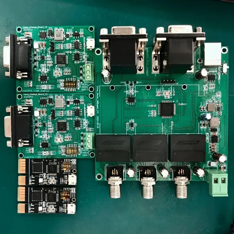
By following the aforementioned plan and standard PCB manufacturing procedures, we successfully produced a 400G optical module PCB, as shown in Figure 7.
This product is packaged in a quad small form-factor pluggable-double density (QSFP-DD) form factor, which is an upgraded version of the high-speed QSFP optical module interface.
It uses optical fiber as the signal transmission medium, converting digital signals into optical signals for fiber-optic transmission, and supports high-speed 400G signal transmission.

Conclusion
Through preliminary planning and design of optical module PCB products (including layer-up design, process flow design, and critical process design), and by effectively addressing key challenges during the manufacturing process, this paper successfully achieved mass production of these optical module PCB products, laying a solid foundation for the future production of high-speed optical module PCBs.