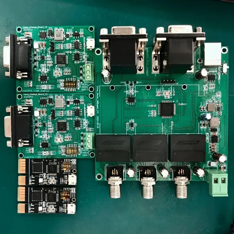
For the subsequent component assembly—especially manual assembly—a PCB assembly drawing is typically created to guide component placement and positioning. This is where silkscreen part numbers prove essential.
Beginners in PCB design have surely encountered this situation: manually adjusting the silkscreen part numbers one by one, which is a tedious, monotonous, and inefficient process.
So, is there a better solution?
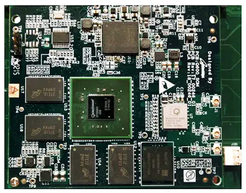
During production, the silkscreen part numbers on the PCB can be shown or hidden, but this does not affect the output of the assembly drawing.
Press the shortcut key “L,” click the “Turn Off All Layers” button to turn off all layers, and then individually check only the silkscreen layer and the corresponding solder mask layer to adjust the silkscreen.
Silkscreen Part Numbers
The following are the principles for adjusting silkscreen part numbers and the recommended standard dimensions:
(1) Silkscreen part numbers are not covered by solder mask; if placed on the silkscreen, they will be missing after production.
(2) Silkscreen part numbers must be clear; recommended character width-to-height ratios are 4/25 mil, 5/30 mil, and 6/45 mil.
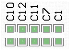
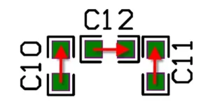
(3) Maintain consistency in orientation; generally, do not place them in more than two different orientations on a single PCB.
It is recommended that letters be positioned on the left or at the bottom, as shown in Figure 11-21.
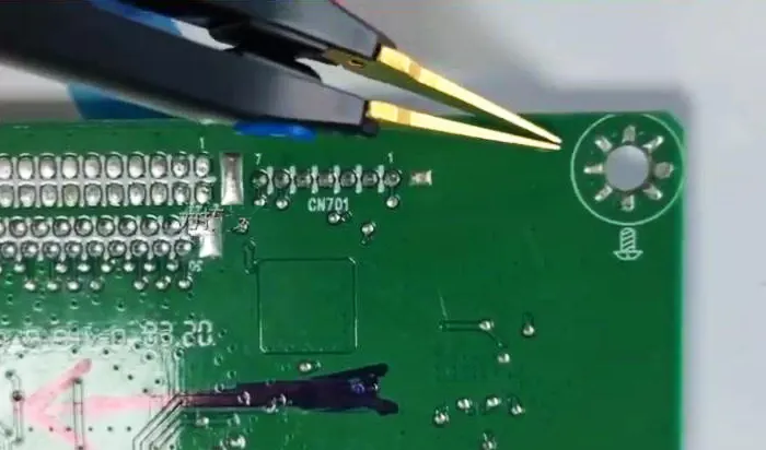
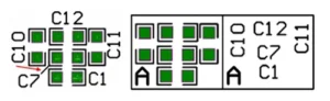
(4) For some screen-printed markings that are difficult to locate, you can add 2D guide lines or place blocks to mark them, making them easier to read, as shown in Figure 11-22.
How to Adjust Silkscreen Label Positions
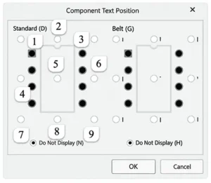
Altium Designer provides a quick way to adjust silkscreen labels using the “Component Text Position” feature, which allows you to quickly place a component’s silkscreen label around the perimeter or in the center of the component.
(1) Select the component you want to edit.
(2) Press the “AP” shortcut key to open the “Component Text Position” dialog box, as shown in Figure 11-23.
This dialog box offers two placement options: “Identifier” and “Comment.” Here, we’ll use “Identifier” as an example.
(3) The “Identifier” option provides several directions—up, down, right, left, top-left, bottom-left, top-right, and bottom-right—which correspond to the number keys on the numeric keypad.
By setting a shortcut key for the “Component Text Position” command, you can quickly place the silkscreen part number of the selected component above it by pressing the number keys “5” and “2” on the numeric keypad, as shown in Figure 11-24.
Placement in other directions works similarly. For example, press the number keys “5” and “6” to place the silkscreen number to the right of the component, and press “5” and “8” to place it below the component.